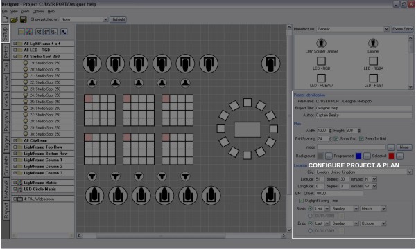
With no fixtures selected, the Project Properties pane is displayed:
The project filename (*.pdp) and path is displayed for reference.
Underneath are two fields for optionally entering a project title and the project's author, these fields are displayed on the Controller's web interface home page and are useful for reference once the installation completed.
If the title field is left blank the web interface will instead display the project's filename which may be useful for tracking iterative versions.
The plan size can be set via the Width and Height fields (in pixels) and a solid background colour selected by clicking the Background browse button. The maximum plan size is 8192x8192 pixels.
The spacing of the working grid can be specified (again in pixels) and there are options to show this grid and whether fixtures should snap to it. This grid is useful in accurately and easily placing fixtures.
To use a background image click on the button next to the Image entry to browse for an image, either a Windows (*.bmp), Portable Network Graphics (*.png) or JPEG (*.jpg) image can be imported. It is envisaged that this image be a graphical representation of the installation, perhaps derived from architectural CAD drawings.
Use the Windows Alt + Print Screen command to take a screen shot of your CAD application and then use a bitmap editor to crop and resize the image to suit (see scale). Again, the maximum plan size is 8192x8192 pixels so make sure the bitmap is smaller or equal to these values. The plan size will automatically adjust to be that of this image.
When planning a fixture layout, give consideration to fixture selection and visualization. Particularly with large layouts, an abstracted arrangement of fixtures may be easier to view and work with than a pixel perfect, scale accurate representation.
The Pharos Designer fixture library uses a scale of 1cm:1pixel (0.394":1pixel) for the fixture icons so, for best results, the plan bitmap should be sized to this scale. If your installation is too large to be accommodated at this scale (i.e. bigger than 81.92m in either axis) then change the scale and use the Fixture Position settings to adjust the scale of your fixture icons accordingly.
It may be desirable to change the colour of programmed and selected fixtures to aid clarity depending on the plan background colour or image, use the browse buttons to select appropriate colours. A darker background makes visualization clearer.
At the bottom are the fields to set the location of the installation to ensure correct operation of the Controller's internal astronomical clocks. A city picker is provided to facilitate the coordinate entry but values can be entered directly into the Latitude and Longitude boxes - a web map service such as www.multimap.com is a useful resource for collecting this information.
The local time zone can be entered as an offset to GMT, for example New York would be -05:00 being 5 hours behind GMT. If the city picker is used to select the location then the time zone will automatically be set.
NOTE: If such an offset is set then the Controller's date and time must be set to GMT not local time or this offset will be doubled.
Check the Daylight Saving Time box to enable automatic DST adjustment. The rules for Daylight Saving differ by region but, if the city picker is used to select the location, the correct settings for that region should appear in the Starts and Ends fields although it is recommended that you check that they are indeed valid. Alternatively, specific dates can be entered (the year is ignored).